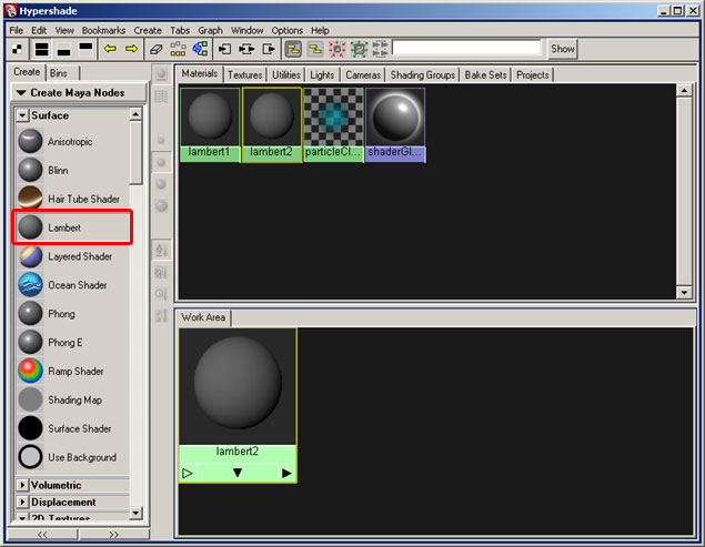
For this type of rigging, we'll need a ground plane to give us some point of reference for our wheel to roll on. The ground should have a texture applied to it to truly emphasize the motion of our wheel. To do that we'll need to open the Hypershade.
|
|
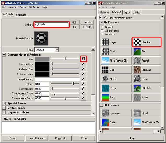
Create a new Lambert shader by choosing "Lambert" from the menu on the left and name it myShader. Set the color to checker pattern by hitting ctrl+a and then selecting a new node for color. When the "Create Render Node" options come up, pick "Checker". You can rename your shader here too. |
|
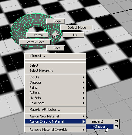
Create a ground plane and a poly Torus from the "Create Polygon Primitives" menu. To assign the new shader to both of them, select each one and hold down the right mouse button .You'll see a pop-up menu that will provide options to set an existing material. |
 |
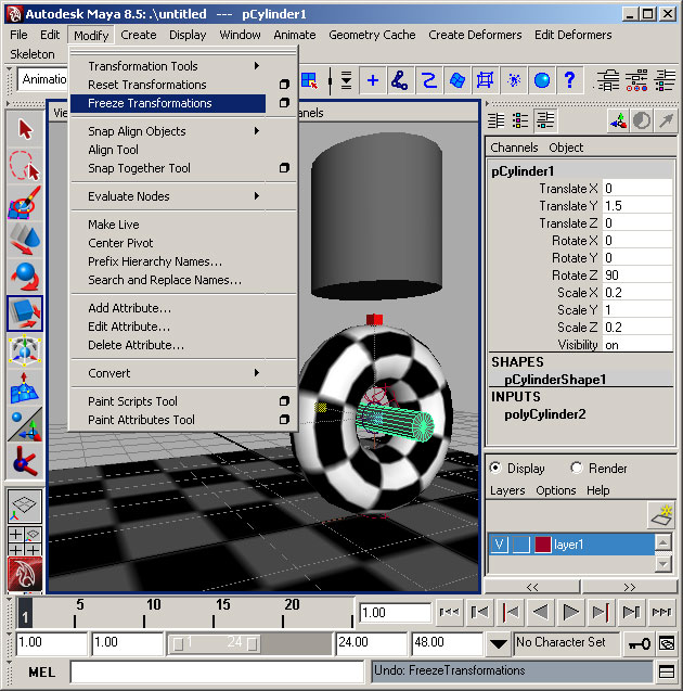
Rename the poly Torus "Wheel" and turn it on it's side. Its ideal attributes are 0, 1.5, 0 for translate values and 0, 0, 90 for rotation. Place a joint in the center (same translate attributes) and make the Torus a child of the joint. This will be our point of rotation for the wheel. Rename the joint "axle" so we can find it later.
|
|
The next step will be much easier in the side view camera in x-ray mode. Now we just need to set up our shock absorber. To do this, create a 3 bone chain in the side view so that the joints make a 90 degree bend starting at 0,2,0, bending at 1,0,0 and ending at 0,0,0. Holding down the "x" key while you place your joints will help them snap to the grid. Now pick the IK tool from the Animation tab  and make an IK chain by first clicking the top joint, then the bottom. We can return to the perspective view now. and make an IK chain by first clicking the top joint, then the bottom. We can return to the perspective view now. |
Now, using a normal point constraint (default settings), we'll constrain the handle to the ground plane. We also want to constrain our axle joint to our IK chain, but this constraint is unique. Select the bottom joint in our IK chain and then select our axle joint. Now open the options for our point constraint (the little box next to the point constraint in the menu) and make sure that "Maintain Offset" is checked. Point constrain the joint in the center of our "wheel" in only the Y axis and make sure the "maintain offset" checkbox is checked. This will keep our axle off the ground, yet hold our IK joint and axle joints together. |
|
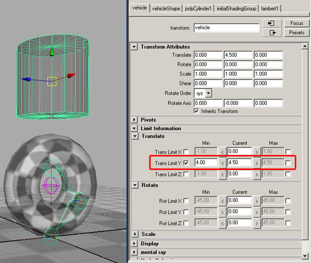
At this point, our rig is already functional. We just need to attach some geometry to show off our work. Make a poly cylinder for our vehicle. Raise it 4.5 units off the grid in translate y. To make sure that it can't crush our wheel, let's set limits on its translate values. You can do this in the attribute editor (ctrl+a). |
|
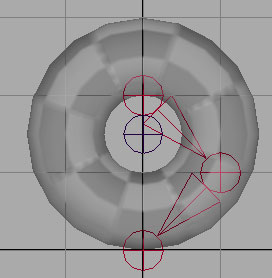
Now select the top joint in our IK chain, shift select our "vehicle" and hit the "p" key. This makes the IK chain a child of the vehicle. At this point you should be able to move the vehicle up and down to see the effects of our rigging. But we're not done yet. Let's make a cylinder and turn it sideways in the center of our "wheel". make it a child of the axle joint. Scale it to fit nicely and freeze its transforms. Forgetting this step will make things weird later. I find the values in the picture below to work pretty well, but precision isn't necessary.
|
 |
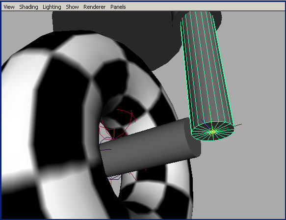
| Now we need our "shocks". The easiest way to make them is by making duplicates of our axle cylinder. With the cylinder selected, hit ctrl+d and make the new duplicate a child of the original. Turn the new cylinder upright and move it to the end of our "axle". Don't freeze the transforms on this one. It should look like this: |
 |
Make one more duplicate, move it straight up and make it slightly larger. This will be our "shock absorber". Make sure this one is visibly larger and make it a child of our "vehicle" geometry. To make it work right, we'll need to move the pivot point of the lower shock to bottom end cap. Do this by selecting the lower shock, hitting "w", and then hitting the "insert" key. Now hold down the "v" key to aid in snapping to the geometry while you move the point to the center of the lower cap. |
 |
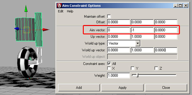
| This is where it gets interesting. We'll use aim constraints to keep the cylinders pointing at each other. Select the top shock, and then shift select the lower cylinder. Select "Aim" from the "Constraint" menu and use default settings. Now select our axle cylinder and shift select the "vehicle" geometry. For this aim constraint we'll need to change the default settings. Make sure to open the options and set up the aim vector like this: |
 |
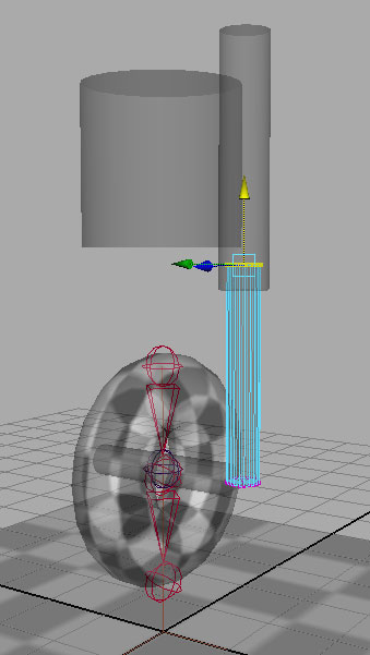
| Move the large cylinder around and see what happens. You may find it necessary to adjust the top ring of verts around the upper end of the lower shock - to keep it from escaping the upper shock geometry when the shock absorber gets hyper-extended. |
 |
To make sure the assembly continues to work, move the vehicle in translate y only (about 6 units should do it). Then pick the lower shock and hit F9 to enter sub-object selection. Now grab the entire top row and move it upward, in translate y only, until the geometry is hidden inside. You may want to be in x-ray mode for this. |
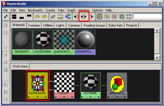
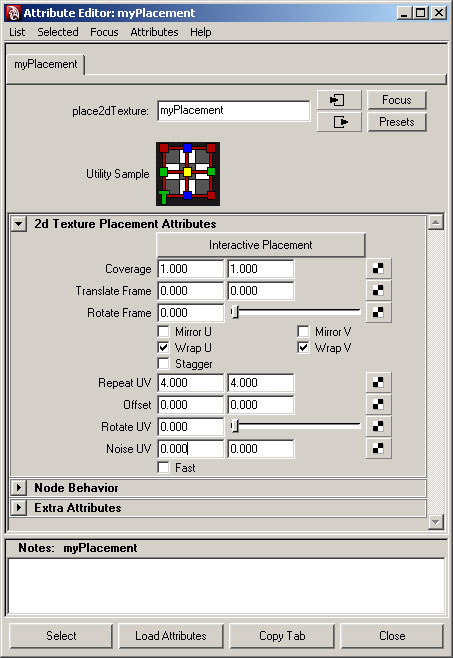
| Now lets have some fun with our creation. Remember that shader we made earlier? Let's go back to that in the hypershade. Select myShader and click the connections button at the top of the hypershade. You'll see a chain of nodes in the bottom window. Double click on the left-most one and rename it "myPlacement". This node is responsible for the placement of the checkers in our scene. Take a moment to play with some of the attributes like "Repeat UV", "Rotate UV", and the one we'll be using - offset. |
 |
 |
| All of these attributes are "keyable" and for even more fun, we can attach an expression to them. Open up the expression editor and add the code below. Press "Create" when you've copied this in there. |
if(!`window -q -exists throttle`)
{window -title "throttle" throttle;
columnLayout;
floatSliderGrp -label "speed" -min 0 -max 5 -v 1 -field true speedCtrl;
showWindow throttle;}
float $speed = `floatSliderGrp -q -v speedCtrl`;
vehicle.translateY = cos(time*5) + 5;
vehicle.translateZ = sin(time*5);
vehicle.translateX = 0;
myPlacement.offsetU = time*$speed; |
After adding this expression, give Maya a few hundred keyframes and press play. If you don't see any motion in the checker pattern, change your panel render settings to "High Quality". The ground plane will have to rotate -90 degrees in y to make things look like the picture, but that won't hurt any of our rigging. This is just to simulate the way shock absorbers would work on a real rig. For actual animation, we'd use keyframes on the vehicle and the ground plane. |
| |